SkyShark TP100 full view

Invitation for Investor(s)

Serious investors are invited to study our information on this site. Real Art GmbH (formerly Aero Visions International, Inc.) has opportunities for financial sources for this highly advanced and potential project to start immediately with prototyping. Interested investors with qualifying financial backgrounds please feel free to read our Investor cover letter. For more information about the designer, check out the aviation credentials.

Interested?

e-mail us for more information and to inquire a business plan for qualified entities
drjuso@aerovisions.com

The SkyShark TP100

Computer rendered CAD images of the latest evolved turbo-prop version design with the PBS turboshaft engine TP100

Design Concept

The following list of pre-defined design requirements was chosen for the Twin-engine concept:

  • Aircraft design to FAR part 23 standards
  • Twin-engine in pusher configuration
  • No critical engine
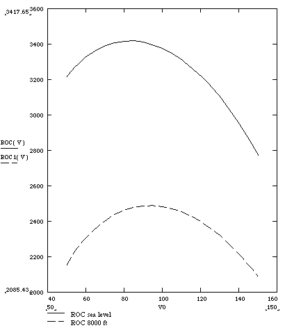
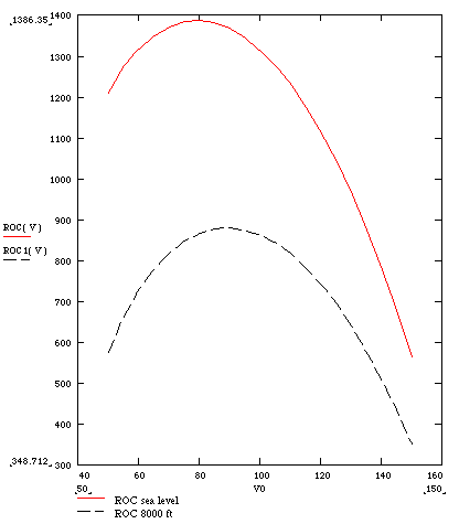
  • Excellent single-engine performance ( > 700 ft/min. climb rate at sea level)
  • Comfortable 4-seat side-by-side seating, future goal of 6 place cabin
  • Excellent outside visual experience and low noise impact for pilots and passengers
  • Greatly reduced noise level in the cabin
  • Empty weight below 2000 lb., gross weight no more than 3000 lb.
  • Baggage weight and volume adequate for four people allowing bulkier items (skis)
  • High-speed performance (target design high cruise speed of 250 kts)
  • Economical and highly efficient (lower than 20 gal on high-speed cruise over 200 kts)
  • Provision for a state-of-the-art de-icing of propeller and wing leading edges
  • Future implementation of a pressurized cabin

Combining these requirements is virtually impossible based on a conventional design or on simple canard concepts. Initial detailed research and studies of a variety of aircraft designs highlighted one spectacular design realized in the beautiful Italian Corporate 11-seat Turboprop Piaggio Avanti P180.

This pressurized, twin-engine, turboprop aircraft provides jet-like speed, high comfort, and an extremely attractive appearance. It's performance and efficiency are based on a three-lifting-surface configuration (TLS), which reduces negative loads on the tail, permitting a 34% reduction in the main wing area and thus proportionate reductions in weight and drag. The pusher concept allows undisturbed airflow over the main wing to enhance laminarity and in turn reduces drag. The forward wing, a canard, helps stall resistance. The basic intelligent concept, therefore, is a substantial drag reduction which leads to the high performance and high efficiency of the Avanti. A slick, extremely aerodynamic fuselage further enhances this aspect. Intrigued by the performance and beauty of the Avanti design, the initial project design criteria leading to the concept of the SkyShark design TP-4 follows consequently a 'scaled-down' version of the Avanti P180.

Another similar design is the Russian Tupolev TU-34, a four-seat STOL surveillance airplane with fixed gear (not yet in production). It incorporates, however, huge lifting surfaces, and therefore is very slow. A recent attempt to integrate the tree-lifting-surface configuration into a production 6-seat design (code name 600-6) with two 300 hp Zoche engines (still not certified) is currently in the early stage of prototyping by a group in Albuquerque. There are many other interesting projects from different categories (certificated and experimental) which incorporate the TLS concept.

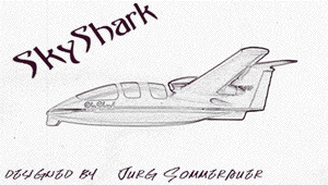
Preliminary calculations of a 'scaled-down model' of the Avanti design revealed strong evidence for the feasibility of such a concept, however, significant modifications of many parameters had to be reconsidered. The present time, the SkyShark project is at the stage of extending the analytical design with control and stability calculation, selection of wing airfoil, and structural analysis. The conceptual design has been successfully completed. Early stages for the construction of the prototype is on the way.

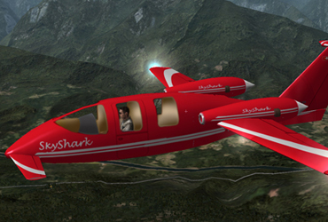
SkyShark TP-4 CAD wireframe

SkyShark TP100 CAD 3d rendering
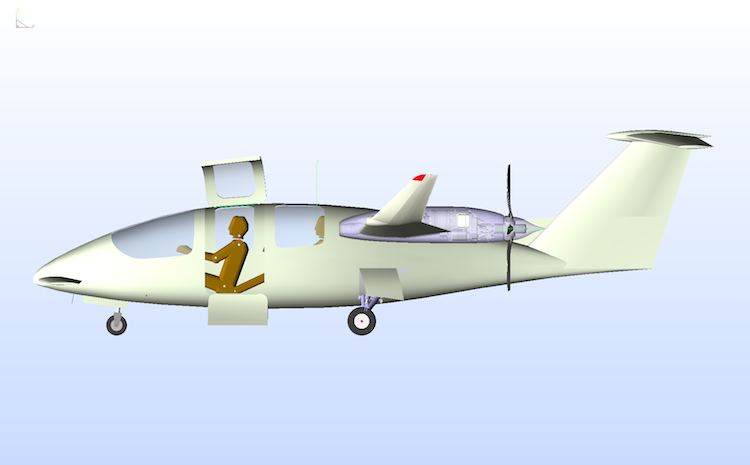
The original performance and efficiency of this Twin engine Pusher 4-seat design concept, named SkyShark TP-4, follows the three-lifting-surface configuration of the Avanti, see Kendall, E.R., ² The Minimum Induced Drag, Longitudinal Trim and Static Longitudinal Stability of Two-Surface and Three-Surface Airplanes², AIAA 2nd Applied Aerodynamics Conference, AIAA-84, 2164, August 1980. A further discussion of this topic is a paper by Rokhsaz, K. and Selberg, B.P., ³Analytical Study of Three-Surface Lifting Systems², General Aviation Aerodynamics, April 1984.

The three-lifting-surface (TLS) design reduces the negative loads on the tail, common to the conventional aircraft, in turn permitting a substantial wing area reduction. This leads to weight savings and drag reduction. Whereas the Avanti saves approximately 34% of wing area, this might be impractical for a scaled-down aircraft considering the associated wing loading. The Avanti has a wing loading of 67.07 lb./sq. ft which results in an unacceptable stall speed of 93 knots for our design. We project a stall speed of 61 knots (FAA standard for SEL aircraft) which allows a wing loading of about 25 lb./sq. ft. A wing area of 102 sq. ft would be necessary at the target gross weight of 2800 lb. to 3000 lb using slotted flaps. Proportionately the fixed canard wing area calculates to some 12 sq. ft on the scaled-down model. The forward wing, the canard, is a fixed lifting surface, which is set so that it stalls before the main wing does, improving stall resistance.

The canard location needed modification considering a substantial reduction in cabin length and in turn fuselage total length. With a shorter fuselage, the TLS arrangement had to be redefined in order to accommodate a suitable CG range. Yet, the pusher concept with the two power plants in the vicinity of the trailing edge of the wing allows more freedom for placing the CG. The canard-main wing combination places the CG somewhere between the two lifting surfaces. This is where the area of the payload is located allowing a wide range of CG.

The power plants in pusher configuration allow the air to flow undisturbed over the wing section which allows a better laminar flow and in turn lower drag counts.

A traditional T-tail arrangement was implemented providing docile conventional handling characteristics of pitch and yaw control. The size and location of the empennage are strongly influenced by the balance of the TLS while optimizing for the best aerodynamic shape of the fuselage at the projected cabin dimensions.

The reduced wing area required the implementation of a Fowler or at least slotted flap system on the main wing to increase lift. The main flaps are linked with the flaps on the forward wing, the canard, allowing a shallow approach path.

Low drag requirements demand also a retractable gear system. In order to minimize the weight of the gear, both nose gear and main gear were designed into the fuselage with reduced strut length. A pitch angle of more than 15 degrees was considered for safe propeller clearance. Furthermore, a ventral fin protects the propellers and provides better yaw stability at the same time.

Drag reducing factors were studied and analyzed for their contribution to drag reduction and technical feasibility, which is summarized in the following table.

Low drag requirement which results in high performance and efficiency:

  • laminar airflow with a pusher configuration
  • streamlined fuselage
  • nacelles and engine cowling buried and blended in wing
  • small engine size - smaller cowling
  • high aspect ratio
  • high wing loading due to decrease in wing area (advantage 3-lifting -surface)
  • retractable gear placed in the fuselage - smaller and lighter weight

Overall dimensions of the SkyShark were kept between a Glasair III, Lancair VI, and the Cirrus VK 30 as some of the larger kit planes.

A major consideration was to provide the builder with ease of construction. Contributions to this are detachable wings outboard from the engines and system integration into the lower fuselage during the construction time (like Lancair IV, and White Lightning) with the gear in place. This provides greater mobility of the major airframe parts.

It has to be noted that these preliminary design criteria might have to be slightly redefined at a later stage of the project, however, all basic concept goals shall be considered as given.

Twin-Pusher 4-Seat fixed Wing design with a 3-Lifting-Surface Configuration. All data are based on the conceptual design and are subject to necessary design changes.
Note: All data are subject to change at any stage of development program.

Power Plant

Various options were being researched for the design with engines of similar weight ranges. The originally selected engine since the start of the project was the Subaru EJ22 and EJ20 but soon scrapped. Further and surely better options would include Rotary-Diesel engines, Continental IO-360, and turbofans.

Currently, our favorite is a turboprop version of the SkyShark implementing the PBS turboshaft engine TP100, and other viable solutions. The aerodynamics of the SkyShark combine well with a turboprop version for a speed of around 300 kts.

Weights (@ 200 hp each)

Maximum Gross 3000 lb.
Standard Empty (with basic Instruments, EJ22) 1710 lb.
Useful Load 1000 lb.
Main Fuel 90 gal 527 lb.
Auxiliary Fuel (one passenger less) 25 gal
Crew and Passengers 680 lb.
Baggage I and II (max., 120 and 30) 150 lb.

Wing Area and Loading (@ 200 hp each)
Main Wing Area 102.1 sq. ft
Canard Area 8.5 sq. ft
Horizontal Tail Area 20.4 sq. ft
Vertical Tail Area 20.7 sq. ft
Wing Loading (main wing) 27.4 lb./sq. ft
Power Loading (main wing) 6.67 lb./hp

Dimensions

Wing Span 33.0 ft
Wing Aspect Ratio 10.67
Aircraft Length 27.0 ft
Aircraft Height 8.6 ft
Canard Span 6.0 ft
Horizontal Stabilizer Span 9.8 ft
Fuselage Width 52 inches, Height 51 inches Cabin Width:
Pilots 46 inches, Passengers 48 inches, Cabin Height 49 inches, Length 91 inches
Baggage I compartment Volume (45" x 15" x 26") 10 cu. ft
Baggage II compartment Volume (15" x 15" x 84") 14 cu. ft

Miscellaneous

Wetted Area 568 sq. ft
Main Wing Airfoil NACA 747A315 or NACA 65sub2-215
Canard Airfoil NACA 65sub2-212
Tail Airfoil sections NACA 65-012 (HT), NACA 65-015 (VT)

Performance specifications (@ 200 hp each)

Operating limits
Structural Load Limit (normal category) 3.8/-1.5 g
Never Exceed Speed Vne 295 kts
Stall Speed in Landing Configuration Vso 61 kts
Maneuvering Speed Va kts
Maximum Flap Extended Speed Vfe kts
Maximum Landing Gear Extended Speed Vle = Vlo kts

Minimum Control Speed, one engine Vmca kts
Rotation Speed, gross Vr kts
Best Rate of Climb Speed Vy 122 kts
Best Rate of Climb Speed Vyse 108 kts
Best Angle of Climb Speed Vx 105 kts
Best Angle of Climb Speed Vxse 93 kts
Best Glide Speed no engine 103 kts
Best L/D (power off) 15
Service Ceiling Two engines 28000 ft, One engine 17000 ft

Speeds @ (@ 200 hp each)

Maximum Speed at Sea Level 248 kts
Cruising Speed at 8000 ft
75% 245 kts
65% 232 kts
55% 220 kts

Range and fuel consumption (8000 ft) , (@ 200 hp each)

Cruising Range 75% 875 NM
Cruising Range 65% 986 NM
Cruising Range 55% 1100 NM

Specific Fuel Flow at max. Power per engine 0.475 lb./hp (@ 200 hp each)

Fuel Flow 75% 24 gal/h
Fuel Flow 65% 18 gal/h
Fuel Flow 55% 15 gal/h

Rate of climb (@ 200 hp each)

Sea Level, ISA, MTOW
Two Engines 3400 ft/min.
One Engine 1200 ft/min.

Takeoff distance over 50 ft. obstacle (@ 200 hp each)

Sea Level, ISA, MTOW 1080 ft

Landing Distance over 50 ft. obstacle (@ 200 hp each)

Sea Level, ISA, MTOW 1400 ft

Top speed with two engine
(non-turbo, 200 hp engines)

Top speed single engine
(non-turbo, 200 hp engines)

Rate of climb with two engines
(non-turbo, 200 hp engines)

Rate of climb single engine
(non-turbo, 200 hp engines)

The fuselage will be built as a combination of a carbon and Kevlar structure. It is circular to oval shape in cross-section in the cabin and baggage area. The front and aft of the fuselage is a streamlined cone. The tail cone supports the T-tail section.

A front windshield is of one piece bolted to the composite fuselage and is removable. Side windows are provided for the passenger rear seats.

On the left fuselage side, the passenger window is an integral part of the cabin door of 27" width and 72' height. The door splits into two parts. The upper section opens upwards and the lower door half swings downward and serves as a staircase.

In the intersection of the main wing and fuselage is the main fuel tank as a section of the fuselage. This section accommodates also the two engines on a platform with main and rear center spar as a structural unit.

Wing group

The wing group is a three-lifting-surface configuration with a forward wing (canard), an aft fuselage mounted main wing and a horizontal stabilizer at the tail section.

The main wings are mounted slightly above the midsection of the fuselage. The wings are detachable outboard of the power plant. Fowler flaps extend from the power plant 2/3 outboard. Conventional ailerons are placed outboard from the flaps. Wing dihedral is 2o.

The fixed forward wing is attached as a whole unit to the fuselage. It comprises a set of single-slotted flaps which are linked to the movement of the main flap system. The canard has a negative anhedral of some 5 degrees to counteract Dutch rolling.

Empennage

The empennage consists of the T-tail with an anhedral of 5 degrees and a ventral fin. The ventral fin serves as protection at a high pitch angle and for improved stability of yaw control.

Landing gear and brakes

The landing gear is fully retractable and is electro-hydraulically operated. It is an integral part of the fuselage. Doors completely cover the retracted gear, mains, and nose. Shock absorption on all three gear is provided by Oleo struts (air-oil system).

The nose gear retracts forward. For emergency, it can be free-fallen supported by a spring. The main gear retracts aft into the fuselage. It is also emergency operated by free-fall supported with gas springs.

The nose gear is steerable by means of the rudder pedals and is only activated on the ground. When airborne, it centers automatically.

The main wheel assembly uses Matco hydraulically activated disk brakes. The brakes are also used for differential steering. A parking brake is provided.

Propeller

Propellers are of three- to four-blade design and are counter-rotating with the right engine propeller turning counter-clockwise and the left one turning clockwise. The propeller is a constant speed design with a governor of electrical or hydraulic control.

Nacelle/cowling

The cowling and nacelle are of greatest importance for the lowest possible drag count. Therefore with the advantage of liquid cooling, the cowling is designed extremely tight. Air for the liquid cooling is picked up in front of the wing leading edge and conducted through the streamline nacelle to the radiator which is mounted forward of the engine block. Excess air exits through ports on the lower side of the wing. The cowling is streamlined extending in a cone-shaped spinner.

Systems

Flight controls:

All flight controls are activated by means of cables, pulleys, and push-pull tubes with bell cranks. Two side sticks, one on the left PIC armrest and one on the right COP armrest control pitch and roll via cables. The rudder is activated via cables using the rudder pedal (which integrates toe-brakes). The dual-pilot rudder pedal unit is independently adjustable aft and forward to accommodate different pilots (The seats are only shop-adjustable). These primary flight controls are supported by three electrically controlled trim tabs. They are operated by MAC trim motors installed in the respective wing adjacent to the trim tabs. The flap system consists of the main flaps and the forward wing flaps. The main flaps (Fowler flaps) are operated by one motor mounted in the center of the fuselage and linked by two interconnected torque tubes and bellcrank to both left and right flaps. The forward wing flaps are single-slotted flaps operated by one motor located in the wing center section and linked by two interconnected torque tubes. The operation of all flaps is electronically synchronized.

Fuel management:

The main fuel tank is located in the fuselage within the wing center section and contains 50 gal of fuel. Both wing sections contain one wing tank each in a separate compartment within the tubular spar containing 15 gal of fuel each. The fuel is drained from the main tank into the engines. An independent fuel line provides fuel from the wing tanks to the respective engine, selectable as an alternate backup system. Fuel may be transferred from the main tank to the wing tanks and vice versa. The CG does not change with fuel consumption.

Hydraulic system:

The electro-hydraulic power pack is placed between the main gear. For emergency activation, the system features an emergency valve and a hydraulic hand pump.

Electrical system:

The electrical system is energized by a 24 volts DC battery-bus unit.
For safety, the electrical system consists of a dual battery-bus-alternator unit. A major battery is backed up by a smaller auxiliary battery. In case of malfunction of the main system, the auxiliary power system is switched in automatically with is of adequate size maintaining power to the essential equipment. A manual override is provided with a circuit breaker for the main and auxiliary bus in combination with reverse current blocking diodes. The capacity of the auxiliary battery is 25% of the main unit.
The circuit breaker panel is situated on the left side by the PIC.

Recognition lights:

Position and strobe light on the wings and tail as well as high-intensity LED landing and taxi lights are standard equipment.

Pressurization and Environmental System:

This system will have to be engineered and finalized at a later stage of the project.

Oxygen System:

A 10 cu ft oxygen high-pressure cylinder will be installed behind the baggage I compartment. Oxygen is supplied to all occupants by constant flow oxygen masks overhead in a protected center compartment.

De-icing:

A de-icing system will be offered as an option by means of high-tech thin foil heating elements on the leading edges of all lifting surfaces laminated on top of the outside composite skin, protected by a high-temperature primer and paint. On the propeller, the same system is glued to the surface of the blade leading edges.

Avionics and Instrumentation:

Engine monitoring instruments are provided as well as a fuel management system. All other instruments and avionics are optional. An optional instrument panel with suggested instruments is easily customizable.

Antennas:

Provided the fuselage and wing shells are constructed with Kevlar around the antennas, all antennas may be installed internally thus contributing to less drag. If carbon/graphite is used without Kevlar 'windows', the antennas have to be on the outside of the skin similar to metal body airplanes.

Cabin:

Cabin door
The cabin door is placed at the pilot station (possibly a second door might be designed at the passenger station if access from the pilot's seat turns out to be problematic). It is designed as a split door with the upper half (with window) hinged on top and the lower half hinged at the bottom of the fuselage. The upper door has to be opened first. The lower door serves as a step to board the airplane.

Seating
The pilot and co-pilot seats are ground-adjustable longitudinally. The backrest of all seats can be tilted forward for easy access to the passengers and baggage area.

Seat belts
Seat belts and shoulder harnesses for the pilot and copilot are provided. They are attached to hardpoints directly at the fuselage.

Baggage compartments

Baggage I: This compartment is located in the aft fuselage in the main wing area right behind the rear seats and is accessible from the seats by folding the backrest forward. Its volume fills the entire area behind both passenger seats.

Baggage II: This compartment is a square tubing from the baggage I on the fuselage ceiling reachable also from the back seats. Its provision is meant for longer bulkier items, e.g. skis and golf clubs.

Airframe construction

Ease of construction for the first time builder and therefore an extremely reliable and safe product was the primary target. This implies that many parts have to be prefabricated and preassembled in the factory while still complying with the 51% rule. Furthermore all the prefabricated (pre-molded) have to snug-fit as a quality standard.

The wings will have to be detachable ( at least for the construction time, and preferably for subsequent special larger maintenance). Similarly, the canopy will have to be bolted onto the fuselage. A wing consists of the lower half and the upper half shell with the main spar already in place in the lower half.

The horizontal stabilizer comes in two parts, the lower shell and the upper shell which can be assembled at an appropriate time.

The fuselage will be divided into 4 shells (normal kit) or 2 shells (fast built kit), divided into lower fuselage halves and upper fuselage halves including fin section.

A center section with the main spar, rear spar, and main landing gear hardpoints will be preassembled and ready to be installed in the lower fuselage, see page 66 ff. System integration will be done with the upper fuselage aside which will be mounted as the last step after the fin section is completed. Main and nose gear installation will be in an early stage which allows the fuselage to be mobile during construction.

The main wing spar will be pre-fitted with the center section spar at the factory for the highest precision and safety.

After the instruments and avionics are installed and tested, the canopy will be bolted to the fuselage.

Prefabricated airframe parts

All airframe parts come precision pre-molded. The wing is shipped with the carbon tubular spars are in place in the lower wing halves. The center spar section is already preassembled. All necessary hardpoints are an integral part of the airframe and only some correction lay-up will be needed by the builder. The canopy is pre-molded and preassembled to specs and ready. The gear struts come preassembled.